Architectural Overview Diagram
Explanation
Section titled “Explanation”An architectural overview diagram is a high-level picture of a system. It shows the main building blocks inside the system. It also shows the people and other systems outside it. Zimmermann’s Design Practice Repository calls it a container diagram. It records the outcome of the early, big solution-strategy decisions (see the article Solution Strategy).
How it differs from a context diagram. A context diagram shows only the outside: external dependencies, used for scope control and risk management. In the repository, it comes first. The overview diagram goes further. It looks inside the system. It still includes all external interfaces with human users and other systems. So it combines internal structure with context.
What it shows.
- Logical and physical building blocks, at a high level. Other diagrams then refine them.
- Every external interface to users and other systems.
- Client-server splits, such as a Remote User Interface or Distributed Presentation. So it can show client devices on one side and backend parts on the other.
Relation to other models. The C4 container diagram is a simple, high-level, technology-focused view of the shape of the architecture and major technology choices. It corresponds to the overview diagram (see Container Diagram (C4 Level 2)).
Relation to arc42. Section 3 delimits the system from all its communication partners. It also asks you to specify those partners, both users and IT systems. The context part of an overview draws on this. Section 5 includes an overview diagram of the whole system at level 1. It stresses abstraction without disclosing implementation details. The DokChess example chapter gives an architectural overview so readers can understand its important design decisions.
Example
Section titled “Example”A small online shop might draw a box for the system. Inside the box sit a web front end and a backend service. Outside the box sit customers, a payment provider and a shipping provider. Arrows connect customers to the front end, and the backend to the two providers. The diagram stays at this coarse level. It leaves out code and server details.
Trade-offs
Section titled “Trade-offs”The diagram looks inside the system, so it takes more effort than a context diagram. It also has to stay abstract. Implementation details are left to the diagrams that refine it.
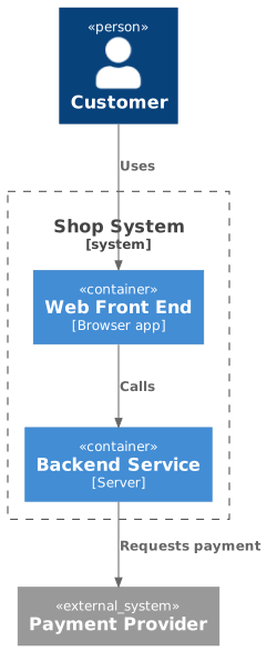
Diagram source
@startuml!include <C4/C4_Container>Person(user, "Customer")System_Boundary(sys, "Shop System") { Container(web, "Web Front End", "Browser app") Container(api, "Backend Service", "Server")}System_Ext(pay, "Payment Provider")Rel(user, web, "Uses")Rel(web, api, "Calls")Rel(api, pay, "Requests payment")@endumlChecks
Section titled “Checks”- The overview diagram includes all external interfaces to human users and other systems.
- The diagram shows building blocks inside the system, not only its external dependencies.
- The diagram stays abstract and does not disclose implementation details.
- All communication partners (users, IT systems) are specified in the context section the overview draws on.
Related
Section titled “Related”- Container Diagram (C4 Level 2)
- Context View
- arc42 Context and Scope
- Solution Strategy
- Architectural Overview Antipattern
- C4 Model
- Component View
Sources
Section titled “Sources”- design-practice-repository | Summaries of artifacts, templates, practices, and techniques for agile architecting (DPR-mm) and service design (SDPR-nn). — socadk.github.io, accessed 2026-11-09
- design-practice-repository | Summaries of artifacts, templates, practices, and techniques for agile architecting (DPR-mm) and service design (SDPR-nn). — socadk.github.io, accessed 2026-11-09
- Container diagram | C4 model — c4model.com, accessed 2026-11-09
- 3 - Context and scope | arc42 Documentation — docs.arc42.org, accessed 2026-11-09
- 5 - Building block view | arc42 Documentation — docs.arc42.org, accessed 2026-11-09
- V - DokChess — arc42 by Example — leanpub.com, accessed 2026-11-09