State Machine Diagram
Explanation
Section titled “Explanation”A state machine diagram draws the life of something as states and transitions. A state is a situation the thing can be in. A transition is a move from one state to another.
Where it starts and ends
- The initial transition starts at a solid circle. It points to the default state.
- A region can have at most one initial vertex, meaning one starting point.
- Entering a final state means the enclosing region has completed.
- Entering a terminate pseudostate stops the whole state machine at once.
Transition labels
A transition label can carry a guard and an effect. The guard is a condition in square brackets. The effect comes after a slash. See State Machine Transition and Transition Syntax (Trigger, Guard, Behavior).
A completion transition has an implicit trigger, so it needs no written event. A time event occurs at a specific point in time.
Behavior inside a state
A state may have an entry behavior, a do behavior and an exit behavior. The entry action runs when the state is entered. The exit action runs whenever the state is left. The do action repeats as long as the state does not change. See State Entry, Exit and Do Behavior.
Branching
- A junction joins several transitions into compound paths.
- A choice is a dynamic conditional branch. If no guard on its outgoing transitions is true, the model is ill formed.
Nesting and reuse
- Composite states contain other states. They can hold several regions that model parallel behavior. See Composite State and Concurrent Region.
- When a composite state is left, exit starts at the innermost active state.
- A submachine state lets you reuse one state machine specification many times. Its connection points match entry and exit points in the referenced machine.
Example
Section titled “Example”Picture a simple online order. It starts in Created. A payment event moves it to Paid, but only if the amount is correct (the guard). The effect sends a receipt. From Paid, a shipping event moves it to Shipped, and then it reaches a final state. The same event, such as “cancel”, could be handled differently in each state.
Trade-offs
Section titled “Trade-offs”Nesting, parallel regions and reusable submachines let you structure large behavior. They also make the diagram harder to read, because exit and entry actions run across state boundaries. A choice whose guards do not cover every case makes the model ill formed. Check that at least one guard is always true.
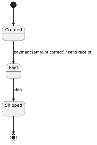
Diagram source
@startuml[*] --> CreatedCreated --> Paid : payment [amount correct] / send receiptPaid --> Shipped : shipShipped --> [*]@endumlChecks
Section titled “Checks”- Each region has at most one initial vertex.
- Every choice pseudostate has outgoing guards that cover all cases, so at least one is true.
- Transition labels write the guard in square brackets and the effect after a slash.
- Any use of a terminate pseudostate is intentional, since it stops the whole state machine immediately.
Related
Section titled “Related”- State Machine Transition
- Transition Syntax (Trigger, Guard, Behavior)
- State Entry, Exit and Do Behavior
- Composite State
- Concurrent Region
- State and Event
- State Machine Diagram Modeling Mistakes
- UML Behavioral Diagram
Sources
Section titled “Sources”- UML state machine - Wikipedia — en.wikipedia.org, accessed 2026-11-09
- Unified Modeling Language 2.5.1 | Webel IT Australia — webel.com.au, accessed 2026-11-09
- UML State Diagram: Sequence of states — sparxsystems.eu, accessed 2026-11-09