Decision Model and Notation
Explanation
Section titled “Explanation”Decision Model and Notation (DMN) is owned by the OMG, a standards body. It gives you two tools for modeling decisions: a graphical notation and an expression language. Its primary goal is a common notation that all business users can understand.
Decisions apart from process flow
DMN is designed to work alongside BPMN, the standard notation for business processes. See BPMN 2.0 Notation for that language. A BPMN business rule task models the evaluation of a business rule. When a process instance reaches such a task, a decision engine evaluates a DMN decision. The process only says when to decide. The decision logic lives in the DMN model. This is how decision logic stays separate from process flow.
Two views of a decision
- Decision Requirements Diagram (DRD). Modeling starts in this view. It is the graphical part of DMN.
- Decision table. This is decision logic shown as a table. It has inputs, outputs and rules. DMN includes decision tables as a built-in feature.
Expressions
DMN also has an expression language, called FEEL. A business knowledge model (BKM) can hold a literal expression. That expression can take parameters, which serve as inputs to the FEEL expression.
Example
Section titled “Example”An online shop wants to decide whether an order needs a manual check. The order process reaches a business rule task named “Check order risk”. The decision engine evaluates a decision table. Its inputs are order amount and customer history. Its output is “manual check” or “auto-approve”. The process then continues along the matching path. A business user can read the table rows without reading the process logic.
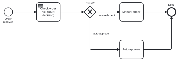
Diagram source
<?xml version="1.0" encoding="UTF-8"?><definitions xmlns="http://www.omg.org/spec/BPMN/20100524/MODEL" xmlns:bpmndi="http://www.omg.org/spec/BPMN/20100524/DI" xmlns:dc="http://www.omg.org/spec/DD/20100524/DC" xmlns:di="http://www.omg.org/spec/DD/20100524/DI" targetNamespace="http://example.com/dmn"> <process id="orderCheck" isExecutable="false"> <startEvent id="s" name="Order received"> <outgoing>f1</outgoing> </startEvent> <businessRuleTask id="t" name="Check order risk (DMN decision)"> <incoming>f1</incoming> <outgoing>f2</outgoing> </businessRuleTask> <exclusiveGateway id="g" name="Result?"> <incoming>f2</incoming> <outgoing>f3</outgoing> <outgoing>f4</outgoing> </exclusiveGateway> <task id="m" name="Manual check"> <incoming>f3</incoming> <outgoing>f5</outgoing> </task> <task id="a" name="Auto-approve"> <incoming>f4</incoming> <outgoing>f6</outgoing> </task> <endEvent id="e" name="Done"> <incoming>f5</incoming> <incoming>f6</incoming> </endEvent> <sequenceFlow id="f1" sourceRef="s" targetRef="t" /> <sequenceFlow id="f2" sourceRef="t" targetRef="g" /> <sequenceFlow id="f3" name="manual check" sourceRef="g" targetRef="m" /> <sequenceFlow id="f4" name="auto-approve" sourceRef="g" targetRef="a" /> <sequenceFlow id="f5" sourceRef="m" targetRef="e" /> <sequenceFlow id="f6" sourceRef="a" targetRef="e" /> </process> <bpmndi:BPMNDiagram id="BPMNDiagram_orderCheck"> <bpmndi:BPMNPlane id="BPMNPlane_orderCheck" bpmnElement="orderCheck"> <bpmndi:BPMNShape id="BPMNShape_s" bpmnElement="s"> <dc:Bounds x="80" y="102" width="36" height="36" /> <bpmndi:BPMNLabel> <dc:Bounds x="68" y="143" width="60" height="28" /> </bpmndi:BPMNLabel> </bpmndi:BPMNShape> <bpmndi:BPMNShape id="BPMNShape_t" bpmnElement="t"> <dc:Bounds x="216" y="80" width="100" height="80" /> </bpmndi:BPMNShape> <bpmndi:BPMNShape id="BPMNShape_g" bpmnElement="g" isMarkerVisible="true"> <dc:Bounds x="416" y="95" width="50" height="50" /> <bpmndi:BPMNLabel> <dc:Bounds x="414" y="76" width="55" height="14" /> </bpmndi:BPMNLabel> </bpmndi:BPMNShape> <bpmndi:BPMNShape id="BPMNShape_m" bpmnElement="m"> <dc:Bounds x="566" y="80" width="100" height="80" /> </bpmndi:BPMNShape> <bpmndi:BPMNShape id="BPMNShape_a" bpmnElement="a"> <dc:Bounds x="566" y="240" width="100" height="80" /> </bpmndi:BPMNShape> <bpmndi:BPMNShape id="BPMNShape_e" bpmnElement="e"> <dc:Bounds x="766" y="102" width="36" height="36" /> <bpmndi:BPMNLabel> <dc:Bounds x="767" y="83" width="34" height="14" /> </bpmndi:BPMNLabel> </bpmndi:BPMNShape> <bpmndi:BPMNEdge id="BPMNEdge_f1" bpmnElement="f1"> <di:waypoint x="116" y="120" /> <di:waypoint x="216" y="120" /> </bpmndi:BPMNEdge> <bpmndi:BPMNEdge id="BPMNEdge_f2" bpmnElement="f2"> <di:waypoint x="316" y="120" /> <di:waypoint x="416" y="120" /> </bpmndi:BPMNEdge> <bpmndi:BPMNEdge id="BPMNEdge_f3" bpmnElement="f3"> <di:waypoint x="466" y="120" /> <di:waypoint x="566" y="120" /> <bpmndi:BPMNLabel> <dc:Bounds x="472" y="128" width="88" height="14" /> </bpmndi:BPMNLabel> </bpmndi:BPMNEdge> <bpmndi:BPMNEdge id="BPMNEdge_f5" bpmnElement="f5"> <di:waypoint x="666" y="120" /> <di:waypoint x="766" y="120" /> </bpmndi:BPMNEdge> <bpmndi:BPMNEdge id="BPMNEdge_f4" bpmnElement="f4"> <di:waypoint x="441" y="145" /> <di:waypoint x="441" y="280" /> <di:waypoint x="566" y="280" /> <bpmndi:BPMNLabel> <dc:Bounds x="446" y="206" width="88" height="14" /> </bpmndi:BPMNLabel> </bpmndi:BPMNEdge> <bpmndi:BPMNEdge id="BPMNEdge_f6" bpmnElement="f6"> <di:waypoint x="666" y="280" /> <di:waypoint x="784" y="280" /> <di:waypoint x="784" y="138" /> </bpmndi:BPMNEdge> </bpmndi:BPMNPlane> </bpmndi:BPMNDiagram></definitions>Checks
Section titled “Checks”- Decision logic sits in a DMN model, not inside the process flow; the process calls it through a business rule task.
- Decision tables list their inputs, outputs and rules.
- Modeling of decisions starts from a Decision Requirements Diagram.
Related
Section titled “Related”Sources
Section titled “Sources”- About the Decision Model and Notation Specification Version 1.7 beta — omg.org, accessed 2026-11-09
- About the Decision Model and Notation Specification Version 1.4 — omg.org, accessed 2026-11-09
- Business rule tasks | Camunda 8 Docs — docs.camunda.io, accessed 2026-11-09
- Overview | Camunda 8 Docs — docs.camunda.io, accessed 2026-11-09
- Modeling with DMN | Camunda 8 Docs — docs.camunda.io, accessed 2026-11-09