Core BPMN Element Subset
Explanation
Section titled “Explanation”BPMN (Business Process Model and Notation) offers many symbols. Real models use few of them. Zur Muehlen and Recker (2008) studied 120 BPMN diagrams. They found that analysts use only a small, commonly shared share of the constructs. They suggested that narrowing the language could ease modeling.
A core subset is a practical answer. You pick the elements most models need. You leave the rest out unless a case demands them.
What the core usually contains
- Sequence flow. An arrow between two elements. It sets the order of steps in the process.
- Tasks. Atomic units of work. You combine them to produce a meaningful result.
- Events. A process can catch an event, which means it reacts. It can also throw an event, which means it emits one.
- Subprocesses. Containers for common functionality.
- Pools and lanes (swim lanes). They exist only at the top level of a process or collaboration. You cannot place them inside a subprocess.
For the elements themselves, see BPMN Core Elements, BPMN Swimlane (Pool and Lane) and BPMN Event.
Readability matters more than symbol variety
A small subset helps stakeholders who are not modelers. Camunda names well-chosen labels as the single most important factor for readable models. A small symbol set with clear labels is easier to follow than a rich symbol set with vague names.
Example
Section titled “Example”A team models an order-handling process. They use one pool with two lanes, “Sales” and “Warehouse”. They draw a start event, three tasks, sequence flows between them and an end event. One group of steps sits in a subprocess. They add no other symbols. A business reader can follow the diagram without learning extra notation.
Trade-offs
Section titled “Trade-offs”A small subset makes models easier to create and read. The facts here do not say which exact elements fall outside the core, or how rarely they occur. Check whether a case needs an element outside the subset before you leave it out.
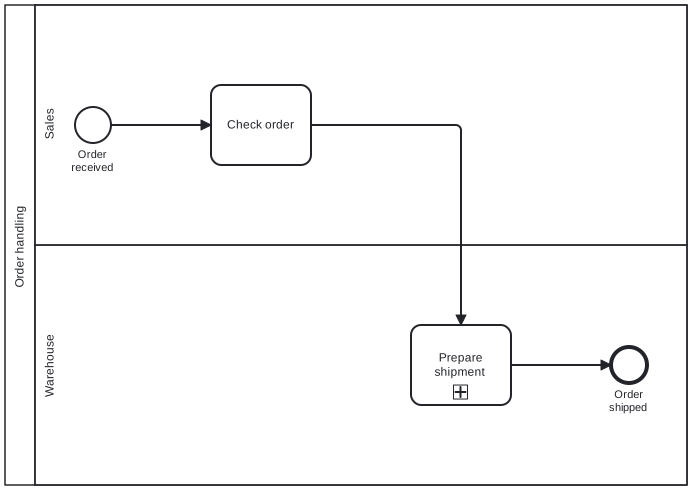
Diagram source
<?xml version="1.0" encoding="UTF-8"?><definitions xmlns="http://www.omg.org/spec/BPMN/20100524/MODEL" xmlns:bpmndi="http://www.omg.org/spec/BPMN/20100524/DI" xmlns:dc="http://www.omg.org/spec/DD/20100524/DC" xmlns:di="http://www.omg.org/spec/DD/20100524/DI" targetNamespace="http://example.com/core"> <collaboration id="c1"> <participant id="p1" name="Order handling" processRef="proc1" /> </collaboration> <process id="proc1" isExecutable="false"> <laneSet id="ls1"> <lane id="l1" name="Sales"> <flowNodeRef>start</flowNodeRef> <flowNodeRef>t1</flowNodeRef> </lane> <lane id="l2" name="Warehouse"> <flowNodeRef>sub</flowNodeRef> <flowNodeRef>end</flowNodeRef> </lane> </laneSet> <startEvent id="start" name="Order received"> <outgoing>sf1</outgoing> </startEvent> <task id="t1" name="Check order"> <incoming>sf1</incoming> <outgoing>sf2</outgoing> </task> <subProcess id="sub" name="Prepare shipment"> <incoming>sf2</incoming> <outgoing>sf3</outgoing> <task id="s1" name="Pick items"> <outgoing>sf4</outgoing> </task> <task id="s2" name="Pack items"> <incoming>sf4</incoming> </task> <sequenceFlow id="sf4" sourceRef="s1" targetRef="s2" /> </subProcess> <endEvent id="end" name="Order shipped"> <incoming>sf3</incoming> </endEvent> <sequenceFlow id="sf1" sourceRef="start" targetRef="t1" /> <sequenceFlow id="sf2" sourceRef="t1" targetRef="sub" /> <sequenceFlow id="sf3" sourceRef="sub" targetRef="end" /> </process> <bpmndi:BPMNDiagram id="BPMNDiagram_c1"> <bpmndi:BPMNPlane id="BPMNPlane_c1" bpmnElement="c1"> <bpmndi:BPMNShape id="BPMNShape_p1" bpmnElement="p1" isHorizontal="true"> <dc:Bounds x="80" y="80" width="682" height="480" /> </bpmndi:BPMNShape> <bpmndi:BPMNShape id="BPMNShape_l1" bpmnElement="l1" isHorizontal="true"> <dc:Bounds x="110" y="80" width="652" height="240" /> </bpmndi:BPMNShape> <bpmndi:BPMNShape id="BPMNShape_l2" bpmnElement="l2" isHorizontal="true"> <dc:Bounds x="110" y="320" width="652" height="240" /> </bpmndi:BPMNShape> <bpmndi:BPMNShape id="BPMNShape_start" bpmnElement="start"> <dc:Bounds x="150" y="182" width="36" height="36" /> <bpmndi:BPMNLabel> <dc:Bounds x="138" y="223" width="60" height="28" /> </bpmndi:BPMNLabel> </bpmndi:BPMNShape> <bpmndi:BPMNShape id="BPMNShape_t1" bpmnElement="t1"> <dc:Bounds x="286" y="160" width="100" height="80" /> </bpmndi:BPMNShape> <bpmndi:BPMNShape id="BPMNShape_sub" bpmnElement="sub"> <dc:Bounds x="486" y="400" width="100" height="80" /> </bpmndi:BPMNShape> <bpmndi:BPMNShape id="BPMNShape_end" bpmnElement="end"> <dc:Bounds x="686" y="422" width="36" height="36" /> <bpmndi:BPMNLabel> <dc:Bounds x="678" y="463" width="53" height="28" /> </bpmndi:BPMNLabel> </bpmndi:BPMNShape> <bpmndi:BPMNEdge id="BPMNEdge_sf1" bpmnElement="sf1"> <di:waypoint x="186" y="200" /> <di:waypoint x="286" y="200" /> </bpmndi:BPMNEdge> <bpmndi:BPMNEdge id="BPMNEdge_sf2" bpmnElement="sf2"> <di:waypoint x="386" y="200" /> <di:waypoint x="536" y="200" /> <di:waypoint x="536" y="400" /> </bpmndi:BPMNEdge> <bpmndi:BPMNEdge id="BPMNEdge_sf3" bpmnElement="sf3"> <di:waypoint x="586" y="440" /> <di:waypoint x="686" y="440" /> </bpmndi:BPMNEdge> </bpmndi:BPMNPlane> </bpmndi:BPMNDiagram> <bpmndi:BPMNDiagram id="BPMNDiagram_sub"> <bpmndi:BPMNPlane id="BPMNPlane_sub" bpmnElement="sub"> <bpmndi:BPMNShape id="BPMNShape_s1" bpmnElement="s1"> <dc:Bounds x="80" y="80" width="100" height="80" /> </bpmndi:BPMNShape> <bpmndi:BPMNShape id="BPMNShape_s2" bpmnElement="s2"> <dc:Bounds x="280" y="80" width="100" height="80" /> </bpmndi:BPMNShape> <bpmndi:BPMNEdge id="BPMNEdge_sf4" bpmnElement="sf4"> <di:waypoint x="180" y="120" /> <di:waypoint x="280" y="120" /> </bpmndi:BPMNEdge> </bpmndi:BPMNPlane> </bpmndi:BPMNDiagram></definitions>Checks
Section titled “Checks”- The document states which BPMN elements the models use, and the set stays small.
- Process steps are labeled with well-chosen, meaningful names.
- Swim lanes appear only at the top level, not inside subprocesses.
Related
Section titled “Related”- BPMN Core Elements
- BPMN Swimlane (Pool and Lane)
- BPMN Event
- BPMN Activity
- BPMN Modeling Guidelines
- BPMN 2.0 Notation
- Process Model Complexity
- BPMN 2.0 Model Quality
Sources
Section titled “Sources”- How much language is enough? Theoretical and practical use of the business process modeling notation - Stevens Institute of Technology — researchwith.stevens.edu, accessed 2026-11-09
- BPMN primer | Camunda 8 Docs — docs.camunda.io, accessed 2026-11-08
- Creating readable process models | Camunda 8 Docs — docs.camunda.io, accessed 2026-11-09