Why Use UML in Architecture Documentation
Explanation
Section titled “Explanation”UML is a graphical language for visualizing, specifying, constructing and documenting systems. The Object Management Group publishes it as a specification (version 2.5.1).
The arc42 authors favor UML for three reasons:
- Many free and commercial tools support it.
- Its symbols have clear meaning.
- It is largely standardized.
Clear meaning matters because readers interpret the diagram the same way. Plain boxes and lines often get read differently by different people. Whatever notation you pick, all stakeholders need a shared understanding of it. Stakeholders are the people with an interest in the system. For the notation itself, see the article “Unified Modeling Language (UML)”.
A concrete case: runtime scenarios. arc42 recommends UML sequence diagrams for runtime scenarios. They show what each participating building block is responsible for. That helps teams discuss the building blocks themselves.
Tooling. Graphical modeling tools can make sequence diagrams laborious to create and manage. PlantUML is a free, open-source, text-based alternative.
Sketches are fine. Martin Fowler notes that most UML diagrams in books are sketches. They communicate selectively and do not try to specify everything.
Alternatives. The C4 model is one alternative. Its FAQ says teams already succeeding with UML, SysML or ArchiMate should keep using them. It also says you can supplement C4 diagrams with UML state or timing diagrams.
Example
Section titled “Example”A team documents how an order is placed. They draw a sequence diagram with three participants: web shop, payment service and warehouse. Each arrow shows which participant asks another to act. Readers can see who is responsible for charging the customer and who reserves the items. The team writes the diagram as PlantUML text, so they can edit it quickly.
Trade-offs
Section titled “Trade-offs”UML does not guarantee a positive effect on your architecture or your team. Other notations may work equally well.
Teams often avoid UML-like notations. They find them too complicated or do not know them well enough. They then fall back on ad hoc box-and-line diagrams, which people interpret differently. If your stakeholders do not know UML, you must make sure they still share an understanding of whatever notation you use.
Graphical modeling tools can add effort. Text-based tools such as PlantUML reduce it.
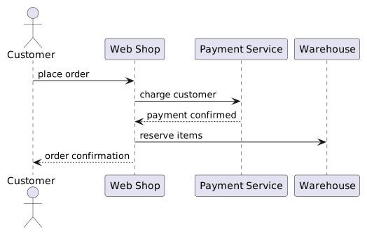
Diagram source
@startumlactor Customerparticipant "Web Shop" as Shopparticipant "Payment Service" as Payparticipant WarehouseCustomer -> Shop : place orderShop -> Pay : charge customerPay --> Shop : payment confirmedShop -> Warehouse : reserve itemsShop --> Customer : order confirmation@endumlChecks
Section titled “Checks”- The documentation states which notation its diagrams use, and stakeholders have a shared understanding of it.
- Runtime scenarios use sequence diagrams (or another notation) that show each building block’s responsibility.
- The documentation does not claim that using UML by itself improves the architecture.
- Where stakeholders find UML too complicated or unfamiliar, the notation choice is justified rather than defaulting to ad hoc box-and-line diagrams.
Related
Section titled “Related”- Unified Modeling Language (UML)
- UML Sequence Diagram
- C4 Model
- Diagrams as Code
- Self-Invented Notation Drawback
- Barriers to UML Adoption
- UML Modeling Best Practice
- UML 2.5 Diagram Taxonomy
Sources
Section titled “Sources”- Question B-3: Shall I use UML for arc42 documentation? | arc42 FAQ — faq.arc42.org, accessed 2026-11-09
- Tip 6-11: Use sequence diagrams to describe or specify runtime scenarios! | arc42 Documentation — docs.arc42.org, accessed 2026-11-09
- Uml As Sketch — martinfowler.com, accessed 2026-11-09
- FAQ | C4 model — c4model.com, accessed 2026-11-09
- About the Unified Modeling Language Specification Version 2.5.1 — omg.org, accessed 2026-11-09