BPMN Layout Guideline
Explanation
Section titled “Explanation”A BPMN diagram shows a business process as boxes and arrows. A layout guideline says how to arrange those shapes on the page. Related articles: BPMN Modeling Guidelines, BPMN Gateway, and Link Event.
Pick one direction. Camunda recommends modeling from left to right. This matches the reading direction of a western audience. Trisotech adds a convention for line types. Sequence flows run horizontally. Message flows and data associations run vertically.
Keep lines short and apart.
- Avoid flows that cross each other. Trisotech says minimizing crossings eases reading.
- Avoid flows that cross many pools or lanes where possible.
- Avoid very long sequence flows, especially ones that run against the reading direction. A link event can replace such a flow.
Draw gateways explicitly.
- Always draw the X marker on an XOR gateway, even if your tool allows a blank one.
- Join alternative paths with an explicit XOR merge gateway. Do not mix split and join meaning in one symbol.
- Place split and join gateway pairs symmetrically.
Name things consistently. Camunda also recommends naming conventions. Labels then convey the business meaning in the same way throughout.
Readability wins. Camunda says not to be dogmatic. If breaking a rule makes the model clearer, aim for the most readable model.
Example
Section titled “Example”Imagine an order process. It starts at the left with “Receive order”. An XOR gateway with an X splits it into “Standard shipping” and “Express shipping”. Both paths run left to right. An explicit XOR merge gateway, placed symmetrically to the split, joins them before “Send invoice”. No arrows cross, and no arrow loops back across the whole page. A reader follows the process from left to right.
Trade-offs
Section titled “Trade-offs”The rules are not absolute. Camunda says explicit modeling should not be dogmatic. A symmetric gateway pair or a short crossing may sometimes hurt readability more than it helps. In that case, choose the clearer diagram.
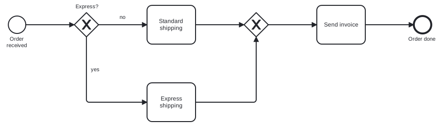
Diagram source
<?xml version="1.0" encoding="UTF-8"?><definitions xmlns="http://www.omg.org/spec/BPMN/20100524/MODEL" xmlns:bpmndi="http://www.omg.org/spec/BPMN/20100524/DI" xmlns:dc="http://www.omg.org/spec/DD/20100524/DC" xmlns:di="http://www.omg.org/spec/DD/20100524/DI" targetNamespace="http://example.com/bpmn"> <process id="order" isExecutable="false"> <startEvent id="s" name="Order received"> <outgoing>f1</outgoing> </startEvent> <exclusiveGateway id="split" name="Express?"> <incoming>f1</incoming> <outgoing>f2</outgoing> <outgoing>f3</outgoing> </exclusiveGateway> <task id="std" name="Standard shipping"> <incoming>f2</incoming> <outgoing>f4</outgoing> </task> <task id="exp" name="Express shipping"> <incoming>f3</incoming> <outgoing>f5</outgoing> </task> <exclusiveGateway id="merge"> <incoming>f4</incoming> <incoming>f5</incoming> <outgoing>f6</outgoing> </exclusiveGateway> <task id="inv" name="Send invoice"> <incoming>f6</incoming> <outgoing>f7</outgoing> </task> <endEvent id="e" name="Order done"> <incoming>f7</incoming> </endEvent> <sequenceFlow id="f1" sourceRef="s" targetRef="split" /> <sequenceFlow id="f2" name="no" sourceRef="split" targetRef="std" /> <sequenceFlow id="f3" name="yes" sourceRef="split" targetRef="exp" /> <sequenceFlow id="f4" sourceRef="std" targetRef="merge" /> <sequenceFlow id="f5" sourceRef="exp" targetRef="merge" /> <sequenceFlow id="f6" sourceRef="merge" targetRef="inv" /> <sequenceFlow id="f7" sourceRef="inv" targetRef="e" /> </process> <bpmndi:BPMNDiagram id="BPMNDiagram_order"> <bpmndi:BPMNPlane id="BPMNPlane_order" bpmnElement="order"> <bpmndi:BPMNShape id="BPMNShape_s" bpmnElement="s"> <dc:Bounds x="80" y="102" width="36" height="36" /> <bpmndi:BPMNLabel> <dc:Bounds x="68" y="143" width="60" height="28" /> </bpmndi:BPMNLabel> </bpmndi:BPMNShape> <bpmndi:BPMNShape id="BPMNShape_split" bpmnElement="split" isMarkerVisible="true"> <dc:Bounds x="216" y="95" width="50" height="50" /> <bpmndi:BPMNLabel> <dc:Bounds x="210" y="76" width="62" height="14" /> </bpmndi:BPMNLabel> </bpmndi:BPMNShape> <bpmndi:BPMNShape id="BPMNShape_std" bpmnElement="std"> <dc:Bounds x="366" y="80" width="100" height="80" /> </bpmndi:BPMNShape> <bpmndi:BPMNShape id="BPMNShape_exp" bpmnElement="exp"> <dc:Bounds x="366" y="240" width="100" height="80" /> </bpmndi:BPMNShape> <bpmndi:BPMNShape id="BPMNShape_merge" bpmnElement="merge" isMarkerVisible="true"> <dc:Bounds x="566" y="95" width="50" height="50" /> </bpmndi:BPMNShape> <bpmndi:BPMNShape id="BPMNShape_inv" bpmnElement="inv"> <dc:Bounds x="716" y="80" width="100" height="80" /> </bpmndi:BPMNShape> <bpmndi:BPMNShape id="BPMNShape_e" bpmnElement="e"> <dc:Bounds x="916" y="102" width="36" height="36" /> <bpmndi:BPMNLabel> <dc:Bounds x="898" y="143" width="73" height="14" /> </bpmndi:BPMNLabel> </bpmndi:BPMNShape> <bpmndi:BPMNEdge id="BPMNEdge_f1" bpmnElement="f1"> <di:waypoint x="116" y="120" /> <di:waypoint x="216" y="120" /> </bpmndi:BPMNEdge> <bpmndi:BPMNEdge id="BPMNEdge_f2" bpmnElement="f2"> <di:waypoint x="266" y="120" /> <di:waypoint x="366" y="120" /> <bpmndi:BPMNLabel> <dc:Bounds x="307" y="98" width="18" height="14" /> </bpmndi:BPMNLabel> </bpmndi:BPMNEdge> <bpmndi:BPMNEdge id="BPMNEdge_f4" bpmnElement="f4"> <di:waypoint x="466" y="120" /> <di:waypoint x="566" y="120" /> </bpmndi:BPMNEdge> <bpmndi:BPMNEdge id="BPMNEdge_f6" bpmnElement="f6"> <di:waypoint x="616" y="120" /> <di:waypoint x="716" y="120" /> </bpmndi:BPMNEdge> <bpmndi:BPMNEdge id="BPMNEdge_f7" bpmnElement="f7"> <di:waypoint x="816" y="120" /> <di:waypoint x="916" y="120" /> </bpmndi:BPMNEdge> <bpmndi:BPMNEdge id="BPMNEdge_f3" bpmnElement="f3"> <di:waypoint x="241" y="145" /> <di:waypoint x="241" y="280" /> <di:waypoint x="366" y="280" /> <bpmndi:BPMNLabel> <dc:Bounds x="246" y="206" width="25" height="14" /> </bpmndi:BPMNLabel> </bpmndi:BPMNEdge> <bpmndi:BPMNEdge id="BPMNEdge_f5" bpmnElement="f5"> <di:waypoint x="466" y="280" /> <di:waypoint x="591" y="280" /> <di:waypoint x="591" y="145" /> </bpmndi:BPMNEdge> </bpmndi:BPMNPlane> </bpmndi:BPMNDiagram></definitions>Checks
Section titled “Checks”- Process diagrams are modeled in one consistent direction, such as left to right.
- Sequence flows do not cross each other, and very long flows are avoided or replaced by link events.
- Every XOR gateway shows the X marker.
- Alternative paths are joined with an explicit XOR merge gateway.
- Naming conventions for BPMN elements are defined and applied.
Related
Section titled “Related”- BPMN Modeling Guidelines
- BPMN Gateway
- Link Event
- BPMN 2.0 Model Quality
- BPMN Gateway Mismatch Antipatterns
- BPMN Connecting Object
- BPMN Swimlane (Pool and Lane)
- BPMN 2.0 Notation
Sources
Section titled “Sources”- Creating readable process models | Camunda 8 Docs — docs.camunda.io, accessed 2026-11-09
- BPMN Modeling Best Practices :: BPMN Quick Guide — cloud.trisotech.com, accessed 2026-11-09