Provided and Required Interface
Explanation
Section titled “Explanation”A component is a building block of a system. It usually works with other building blocks. Two ideas describe how it connects to them: what it offers, and what it needs.
Provided interface. This is what a component offers to others. In a UML component diagram (see UML Component Diagram), it appears as a ball, also called a lollipop. The ball carries the name of the interface. A solid line links it to the component that provides it.
Required interface. This is what a component needs from others. It is a usage dependency. UML draws it as a half-circle, called a socket, attached to the component that has the need.
Who defines it. A common view is that the supplier decides what to expose. A required interface turns this around. The client of an interaction defines it.
Why show them. arc42 recommends ball and socket notation. It makes explicit which services, data, or events a providing building block offers.
Ports. A port is a point on a component where interfaces attach (see Port). arc42 suggests using ball and socket together with port symbols. In a modeling tool, the port shows its provided and required interfaces in ball-socket notation. A realization dependency (provided) or a usage dependency (required) is created from the port type. A port can provide or require many interfaces. It therefore groups them, and you can choose which ones to display.
Example
Section titled “Example”An online shop has an Order component and a Payment component. Payment offers a “Charge” interface, drawn as a ball. Order needs a way to charge customers, so it shows a socket named “Charge”. Reading the diagram, you see that Order depends on Payment through “Charge”. Order’s needs define what “Charge” must contain. Payment provides it.
Trade-offs
Section titled “Trade-offs”Ports group many interfaces, so a diagram can show only some of them. This keeps pictures readable. It also means a reader may not see every interface unless the hidden ones are documented elsewhere.
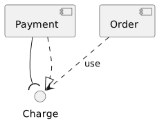
Diagram source
@startumlcomponent Ordercomponent Paymentinterface ChargePayment -( ChargePayment ..|> ChargeOrder ..> Charge : use@endumlChecks
Section titled “Checks”- Provided interfaces are drawn as balls that name the services, data, or events a building block offers.
- Required interfaces are drawn as sockets on the component that depends on them.
- Ball and socket notation is combined with port symbols where a component has several interfaces.
Related
Section titled “Related”- UML Interface
- UML Component Diagram
- Port
- Component Connector (Assembly and Delegation)
- Component View
- Common Component Diagram Mistake
Sources
Section titled “Sources”- Component diagram - Wikipedia — en.wikipedia.org, accessed 2026-11-09
- Question D-5: How can I describe interfaces with UML? | arc42 FAQ — faq.arc42.org, accessed 2026-11-09
- Required Interface — martinfowler.com, accessed 2026-11-09
- Provided and Required Interfaces — docs.nomagic.com, accessed 2026-11-09