Use Case Diagram
Explanation
Section titled “Explanation”A use case diagram gives an overview of the usage requirements for a system (f1). It is a higher-level view of the system (f11). Teams usually begin use case analysis by drawing it (f9).
Main elements
- Actors are people, organizations or external systems. Each plays a role when interacting with the system (f6).
- Use cases describe system behavior. A use case is a structured description of how the system responds to requests from external actors (f7). See the article Use Case.
- System boundary is a box around the use cases. Functionality inside the box is in scope. Anything outside is not (f2).
Use case descriptions can be black-box, where internal detail is hidden, or white-box, where it is shown (f8).
Relationships between use cases
- Include works like a procedure call from the base use case (f3). The base use case calls another one as a step.
- Extend works like a hardware interrupt. You do not know when, or whether, the extending use case will run (f4).
- Inheritance (generalization) models specialization. It works the same way as on class diagrams (f5). It applies to use cases and to actors (f5).
Example
Section titled “Example”A library system has two actors: “Member” and “Catalog System” (an external system). Inside the system box sit the use cases “Borrow Book” and “Search Catalog”. “Borrow Book” includes “Check Member Status”, because every loan needs that step. “Pay Late Fee” extends “Return Book”, because it only happens if the book is late. The diagram shows none of the screens, data or code behind these use cases. It shows only who uses the system and what they can do.
Trade-offs
Section titled “Trade-offs”The diagram stays at a high level (f11). That makes it easy to read, but it does not show how the behavior works. Some relationships, such as extend, can be read in different ways (f10). Readers may then understand the same diagram differently.
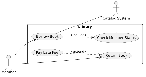
Diagram source
@startumlleft to right directionactor Memberactor "Catalog System" as Catrectangle Library { usecase "Borrow Book" as UC1 usecase "Check Member Status" as UC2 usecase "Return Book" as UC3 usecase "Pay Late Fee" as UC4}Member --> UC1Member --> UC3UC1 ..> UC2 : <<include>>UC4 ..> UC3 : <<extend>>UC1 --> Cat@endumlChecks
Section titled “Checks”- The diagram draws a system boundary, so it is clear which functionality is in scope and which is not.
- Every actor is a person, organization or external system that interacts with the system.
- Extend relationships are used with care, and their meaning is made clear to readers.
Related
Section titled “Related”- Use Case
- Common Use Case Diagram Errors
- UML Behavioral Diagram
- UML Generalization and Specialization
- Use Case Template
- arc42 Context and Scope
- User Stories vs. Use Cases
- UML Association
Sources
Section titled “Sources”- UML Use Case Diagrams: An Agile Introduction — agilemodeling.com, accessed 2026-11-09
- Use case - Wikipedia — en.wikipedia.org, accessed 2026-11-09
- Use case diagram - Wikipedia — en.wikipedia.org, accessed 2026-11-09