BPMN Collaboration Diagram
Explanation
Section titled “Explanation”A collaboration diagram is the BPMN name for a picture in which separate pools exchange messages (see BPMN Swimlane (Pool and Lane)). Each participant gets its own pool. Message flows between the pools show the interaction and communication explicitly.
Pools versus lanes
A pool ranks above its lanes. Lanes always sit inside a pool, and their boundaries are process boundaries from start to end. For operational-level models, Camunda recommends separate pools for the participants instead of lanes. It also advises avoiding lanes in most models, because lanes make changes harder to maintain.
What separate pools show
Separate pools show who controls which process. Processes that run at different frequencies belong in separate pools.
Collapsed pools
A pool can be collapsed when the other party’s internal process is of little interest. A customer, for example, has little interest in how a deliverer works inside.
Messages and signals
A message goes to a specific recipient. A signal is a broadcast: any receiver that wants to react may do so. Signals are compact for interaction between process instances. But they do not address any specific instance.
Layout
Order the pools so that message flows cross other pools as little as possible.
Example
Section titled “Example”A customer orders a meal from a restaurant. The diagram has two pools: “Customer” and “Restaurant”. The customer pool is expanded. The restaurant pool is collapsed, because the customer does not care how the kitchen works. A dashed message flow carries the order to the restaurant. Another dashed flow carries the confirmation back.
Trade-offs
Section titled “Trade-offs”Separate pools make interaction explicit and show who controls each process. The cost is more pools to arrange, and you must order them so message flows do not cross other pools. Lanes look simpler, but Camunda advises avoiding them in most models because they make changes harder to maintain. A signal is compact, but it cannot address one specific instance.
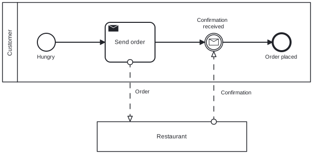
Diagram source
<?xml version="1.0" encoding="UTF-8"?><definitions xmlns="http://www.omg.org/spec/BPMN/20100524/MODEL" xmlns:bpmndi="http://www.omg.org/spec/BPMN/20100524/DI" xmlns:dc="http://www.omg.org/spec/DD/20100524/DC" xmlns:di="http://www.omg.org/spec/DD/20100524/DI" targetNamespace="http://example.org/bpmn"> <collaboration id="c1"> <participant id="pCustomer" name="Customer" processRef="customerProcess" /> <participant id="pRestaurant" name="Restaurant" /> <messageFlow id="m1" name="Order" sourceRef="sendOrder" targetRef="pRestaurant" /> <messageFlow id="m2" name="Confirmation" sourceRef="pRestaurant" targetRef="waitConfirm" /> </collaboration> <process id="customerProcess" isExecutable="false"> <startEvent id="s1" name="Hungry"> <outgoing>sf1</outgoing> </startEvent> <sendTask id="sendOrder" name="Send order"> <incoming>sf1</incoming> <outgoing>sf2</outgoing> </sendTask> <intermediateCatchEvent id="waitConfirm" name="Confirmation received"> <incoming>sf2</incoming> <outgoing>sf3</outgoing> <messageEventDefinition /> </intermediateCatchEvent> <endEvent id="e1" name="Order placed"> <incoming>sf3</incoming> </endEvent> <sequenceFlow id="sf1" sourceRef="s1" targetRef="sendOrder" /> <sequenceFlow id="sf2" sourceRef="sendOrder" targetRef="waitConfirm" /> <sequenceFlow id="sf3" sourceRef="waitConfirm" targetRef="e1" /> </process> <bpmndi:BPMNDiagram id="BPMNDiagram_c1"> <bpmndi:BPMNPlane id="BPMNPlane_c1" bpmnElement="c1"> <bpmndi:BPMNShape id="BPMNShape_pCustomer" bpmnElement="pCustomer" isHorizontal="true"> <dc:Bounds x="80" y="80" width="618" height="160" /> </bpmndi:BPMNShape> <bpmndi:BPMNShape id="BPMNShape_pRestaurant" bpmnElement="pRestaurant" isHorizontal="true"> <dc:Bounds x="270" y="320" width="300" height="60" /> </bpmndi:BPMNShape> <bpmndi:BPMNEdge id="BPMNEdge_m1" bpmnElement="m1"> <di:waypoint x="336" y="200" /> <di:waypoint x="336" y="320" /> <bpmndi:BPMNLabel> <dc:Bounds x="341" y="253" width="41" height="14" /> </bpmndi:BPMNLabel> </bpmndi:BPMNEdge> <bpmndi:BPMNEdge id="BPMNEdge_m2" bpmnElement="m2"> <di:waypoint x="504" y="320" /> <di:waypoint x="504" y="178" /> <bpmndi:BPMNLabel> <dc:Bounds x="509" y="255" width="86" height="28" /> </bpmndi:BPMNLabel> </bpmndi:BPMNEdge> <bpmndi:BPMNShape id="BPMNShape_s1" bpmnElement="s1"> <dc:Bounds x="150" y="142" width="36" height="36" /> <bpmndi:BPMNLabel> <dc:Bounds x="144" y="183" width="48" height="14" /> </bpmndi:BPMNLabel> </bpmndi:BPMNShape> <bpmndi:BPMNShape id="BPMNShape_sendOrder" bpmnElement="sendOrder"> <dc:Bounds x="286" y="120" width="100" height="80" /> </bpmndi:BPMNShape> <bpmndi:BPMNShape id="BPMNShape_waitConfirm" bpmnElement="waitConfirm"> <dc:Bounds x="486" y="142" width="36" height="36" /> <bpmndi:BPMNLabel> <dc:Bounds x="461" y="109" width="86" height="28" /> </bpmndi:BPMNLabel> </bpmndi:BPMNShape> <bpmndi:BPMNShape id="BPMNShape_e1" bpmnElement="e1"> <dc:Bounds x="622" y="142" width="36" height="36" /> <bpmndi:BPMNLabel> <dc:Bounds x="597" y="183" width="87" height="14" /> </bpmndi:BPMNLabel> </bpmndi:BPMNShape> <bpmndi:BPMNEdge id="BPMNEdge_sf1" bpmnElement="sf1"> <di:waypoint x="186" y="160" /> <di:waypoint x="286" y="160" /> </bpmndi:BPMNEdge> <bpmndi:BPMNEdge id="BPMNEdge_sf2" bpmnElement="sf2"> <di:waypoint x="386" y="160" /> <di:waypoint x="486" y="160" /> </bpmndi:BPMNEdge> <bpmndi:BPMNEdge id="BPMNEdge_sf3" bpmnElement="sf3"> <di:waypoint x="522" y="160" /> <di:waypoint x="622" y="160" /> </bpmndi:BPMNEdge> </bpmndi:BPMNPlane> </bpmndi:BPMNDiagram></definitions>Checks
Section titled “Checks”- Operational-level process models use a separate pool per participant instead of lanes.
- Interaction between participants is shown with message flows between pools.
- Pools are ordered so message flows cross other pools as little as possible.
- Pools of parties whose internal process is of little interest are collapsed.
- Processes with different frequencies are modeled in separate pools.
Related
Section titled “Related”- BPMN Swimlane (Pool and Lane)
- BPMN Diagram Types
- BPMN Conversation Diagram
- Data Exchange between BPMN Processes
- BPMN Layout Guideline
- BPMN Event
- Levels of Process Modeling
- BPMN 2.0 Notation
Sources
Section titled “Sources”- Creating readable process models | Camunda 8 Docs — docs.camunda.io, accessed 2026-11-09
- BPMN 2.0 Symbols - A complete guide with examples. | Camunda — camunda.com, accessed 2026-11-09
- BPMN 2.0 Examples | Camunda — camunda.com, accessed 2026-11-09