UML Class Diagram
Explanation
Section titled “Explanation”A class diagram shows classes and the links between them. See UML Class Diagram Relationship for the full set of relationship types.
Associations. An association is a line between two classes. It usually stands for something like a field in a class. If class A holds a reference to class B, you draw an association from A to B.
Dependencies. A dependency means that a change to one element (the supplier) may force a change in another (the client). Associations and generalizations already imply a dependency. So there is no need to draw an extra dependency line next to them.
Interfaces. UML 2 added the socket notation to show interfaces a class requires. It grew out of the lollipop notation, which shows interfaces a class provides. The UML committee ruled that the combined ball-and-socket notation may only be used for connectors in Composite Structure Diagrams. It does not link interfaces in class diagrams. See Provided and Required Interface for more.
Stay selective. Use class diagrams as sketches. Show only the classes that are interesting and worth discussing before you read the code. The goal is communication, not a complete specification. Showing every class makes the diagram harder to understand.
Example
Section titled “Example”A team sketches an online shop. The diagram shows three classes: Order, Customer and Product. An association from Order to Customer reflects that an order holds a reference to its customer. Helper classes stay out of the picture. The team uses the sketch to agree on the core ideas before looking at code.
Trade-offs
Section titled “Trade-offs”A selective sketch is quick to read and good for discussion. It leaves classes out, so it is not a complete specification. Drawing every class would be more complete, but it would hurt comprehensibility.
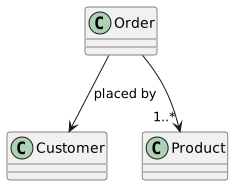
Diagram source
@startumlclass Orderclass Customerclass ProductOrder --> Customer : placed byOrder --> "1..*" Product@endumlChecks
Section titled “Checks”- The class diagram shows only the interesting classes, not every class in the system.
- Dependency lines are not drawn in addition to associations or generalizations between the same classes.
- The ball-and-socket notation is not used to link interfaces in class diagrams.
Related
Section titled “Related”- UML Class Diagram Relationship
- UML Association
- Aggregation vs. Composition
- UML Generalization and Specialization
- Provided and Required Interface
- UML Interface
- Common Class Diagram Modeling Mistakes
- UML Structure Diagram
Sources
Section titled “Sources”- Uml As Sketch — martinfowler.com, accessed 2026-11-09
- Dependency And Association — martinfowler.com, accessed 2026-11-09
- Ball And Socket — martinfowler.com, accessed 2026-11-09