BPMN Modeling Guidelines
Explanation
Section titled “Explanation”BPMN is a notation for drawing business processes. See the article BPMN 2.0 Notation for the basics. The rules below come from Camunda’s documentation and from Silver’s Method and Style.
Keep each model small. Silver’s style allows about 10 activities in one process level, so the model fits on one printed page. For more detail, use subprocesses: an activity that hides a smaller process inside it. Also avoid very long sequence flows that span pages or run against the reading direction.
Show start and end events. Always draw them explicitly. Readers then see what triggers the process and how it ends. A message start event is labeled “Receive” plus the message name. Events are named with an object plus a verb that describes a state. So an end event states the resulting state, such as “Invoice paid”. In Silver’s style, end events stand for distinct end states of a process or subprocess.
Connect subprocess and parent. After a collapsed subprocess, the parent level uses an XOR gateway. Its gates match the subprocess’s end event labels.
Phrase XOR gateways as questions. An XOR gateway picks exactly one path. Label it with a question. Label each outgoing flow as an answer to that question. Draw the X symbol inside the gateway, even if your tool allows a blank one.
Leave some gateways unnamed. Camunda advises against naming parallel gateways and all joining gateways. Silver’s style also leaves AND and event gateways unlabeled, including their gates.
Name tasks as actions. Camunda asks for an object and a verb in the infinitive, for example “Check invoice”. Silver wants all activities, subprocesses included, labeled as verb-object actions.
Use pools for participants. Give each participant its own pool. Name a pool after the process it contains. Order the pools so message flows cross other pools as little as possible.
Example
Section titled “Example”An order process starts with the message start event “Receive order”. The task “Check stock” leads to an XOR gateway named “Is the item in stock?”. The branches are labeled “Yes” and “No”. “Yes” leads to the task “Ship order” and the end event “Order shipped”. “No” leads to the end event “Order rejected”. The two end events show two different end states.
Trade-offs
Section titled “Trade-offs”Limiting a level to about 10 activities pushes detail into subprocesses. Readers must then open several models to see the full process. Explicit end events and gateway gates add drawing effort. They also keep the model unambiguous.
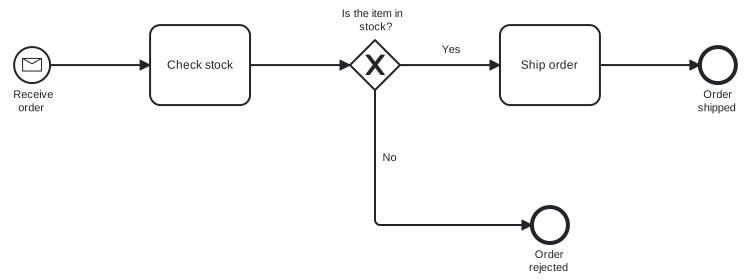
Diagram source
<?xml version="1.0" encoding="UTF-8"?><definitions xmlns="http://www.omg.org/spec/BPMN/20100524/MODEL" xmlns:bpmndi="http://www.omg.org/spec/BPMN/20100524/DI" xmlns:dc="http://www.omg.org/spec/DD/20100524/DC" xmlns:di="http://www.omg.org/spec/DD/20100524/DI" targetNamespace="http://example.com/bpmn"> <process id="p1" isExecutable="false"> <startEvent id="s" name="Receive order"> <outgoing>f1</outgoing> <messageEventDefinition /> </startEvent> <task id="t1" name="Check stock"> <incoming>f1</incoming> <outgoing>f2</outgoing> </task> <exclusiveGateway id="g" name="Is the item in stock?"> <incoming>f2</incoming> <outgoing>f3</outgoing> <outgoing>f4</outgoing> </exclusiveGateway> <task id="t2" name="Ship order"> <incoming>f3</incoming> <outgoing>f5</outgoing> </task> <endEvent id="e1" name="Order shipped"> <incoming>f5</incoming> </endEvent> <endEvent id="e2" name="Order rejected"> <incoming>f4</incoming> </endEvent> <sequenceFlow id="f1" sourceRef="s" targetRef="t1" /> <sequenceFlow id="f2" sourceRef="t1" targetRef="g" /> <sequenceFlow id="f3" name="Yes" sourceRef="g" targetRef="t2" /> <sequenceFlow id="f4" name="No" sourceRef="g" targetRef="e2" /> <sequenceFlow id="f5" sourceRef="t2" targetRef="e1" /> </process> <bpmndi:BPMNDiagram id="BPMNDiagram_p1"> <bpmndi:BPMNPlane id="BPMNPlane_p1" bpmnElement="p1"> <bpmndi:BPMNShape id="BPMNShape_s" bpmnElement="s"> <dc:Bounds x="80" y="102" width="36" height="36" /> <bpmndi:BPMNLabel> <dc:Bounds x="71" y="143" width="55" height="28" /> </bpmndi:BPMNLabel> </bpmndi:BPMNShape> <bpmndi:BPMNShape id="BPMNShape_t1" bpmnElement="t1"> <dc:Bounds x="216" y="80" width="100" height="80" /> </bpmndi:BPMNShape> <bpmndi:BPMNShape id="BPMNShape_g" bpmnElement="g" isMarkerVisible="true"> <dc:Bounds x="416" y="95" width="50" height="50" /> <bpmndi:BPMNLabel> <dc:Bounds x="401" y="62" width="80" height="28" /> </bpmndi:BPMNLabel> </bpmndi:BPMNShape> <bpmndi:BPMNShape id="BPMNShape_t2" bpmnElement="t2"> <dc:Bounds x="566" y="80" width="100" height="80" /> </bpmndi:BPMNShape> <bpmndi:BPMNShape id="BPMNShape_e1" bpmnElement="e1"> <dc:Bounds x="766" y="102" width="36" height="36" /> <bpmndi:BPMNLabel> <dc:Bounds x="758" y="143" width="53" height="28" /> </bpmndi:BPMNLabel> </bpmndi:BPMNShape> <bpmndi:BPMNShape id="BPMNShape_e2" bpmnElement="e2"> <dc:Bounds x="598" y="262" width="36" height="36" /> <bpmndi:BPMNLabel> <dc:Bounds x="586" y="303" width="60" height="28" /> </bpmndi:BPMNLabel> </bpmndi:BPMNShape> <bpmndi:BPMNEdge id="BPMNEdge_f1" bpmnElement="f1"> <di:waypoint x="116" y="120" /> <di:waypoint x="216" y="120" /> </bpmndi:BPMNEdge> <bpmndi:BPMNEdge id="BPMNEdge_f2" bpmnElement="f2"> <di:waypoint x="316" y="120" /> <di:waypoint x="416" y="120" /> </bpmndi:BPMNEdge> <bpmndi:BPMNEdge id="BPMNEdge_f3" bpmnElement="f3"> <di:waypoint x="466" y="120" /> <di:waypoint x="566" y="120" /> <bpmndi:BPMNLabel> <dc:Bounds x="503" y="98" width="27" height="14" /> </bpmndi:BPMNLabel> </bpmndi:BPMNEdge> <bpmndi:BPMNEdge id="BPMNEdge_f5" bpmnElement="f5"> <di:waypoint x="666" y="120" /> <di:waypoint x="766" y="120" /> </bpmndi:BPMNEdge> <bpmndi:BPMNEdge id="BPMNEdge_f4" bpmnElement="f4"> <di:waypoint x="441" y="145" /> <di:waypoint x="441" y="280" /> <di:waypoint x="598" y="280" /> <bpmndi:BPMNLabel> <dc:Bounds x="446" y="206" width="20" height="14" /> </bpmndi:BPMNLabel> </bpmndi:BPMNEdge> </bpmndi:BPMNPlane> </bpmndi:BPMNDiagram></definitions>Checks
Section titled “Checks”- Each process level has about 10 activities or fewer, so it fits on one page.
- Every process shows explicit start and end events.
- XOR gateways show the X symbol, carry a question, and have outgoing flows labeled as answers.
- Tasks are named with a verb and an object.
- Parallel and joining gateways carry no name.
Related
Section titled “Related”- BPMN 2.0 Notation
- BPMN Layout Guideline
- BPMN 2.0 Model Quality
- BPMN Gateway
- BPMN Collaboration Diagram
- BPMN Swimlane (Pool and Lane)
- Levels of Process Modeling
- BPMN Gateway Mismatch Antipatterns
Sources
Section titled “Sources”- Naming BPMN elements | Camunda 8 Docs — docs.camunda.io, accessed 2026-11-09
- Creating readable process models | Camunda 8 Docs — docs.camunda.io, accessed 2026-11-09
- BPMN Style Rules — trisotech.com, accessed 2026-11-09