Business Object Lifecycle
Explanation
Section titled “Explanation”Most process models center on activities: what people or systems do, in which order. The artifact-centric (or data-centric) approach is an alternative. It centers on the business objects themselves, such as an application, an invoice, or a rental car.
Lifecycle as a state machine. Each object has a lifecycle: the states it can be in and how it moves between them. You can draw a lifecycle as a statechart or a UML-style state machine diagram. See the articles State Machine Diagram and State and Event.
Processes change states. In this view, a process is a service that changes objects. Associations between the process and the object set limits on how the process may change the object. So the lifecycle restricts what a process is allowed to do.
Events are states. In ARIS event-driven process chains, an event is a business-relevant state. It controls how one or more processes continue. State changes show up as changes in the status of an information object. So an object’s state and a process event are closely linked.
Why not only activities? Real systems often hold many instances of several objects. These instances run in parallel and relate to each other in complex ways. A classical single activity flow cannot represent this.
See Process Notations Comparison for how EPC, BPMN and UML activity diagrams compare.
Example
Section titled “Example”Take a rental car. Its lifecycle might have the states “available”, “rented” and “in maintenance”. A “return car” process moves it from “rented” to “available”. The state “available” can act as an event that lets the next booking proceed. Each car has its own state, even when many cars are handled at the same time.
Trade-offs
Section titled “Trade-offs”The facts show one clear reason to choose this approach: a single activity flow cannot capture complex object dynamics, such as parallel instances with relationships. They do not describe costs of the approach, so weigh it against your own modeling needs.
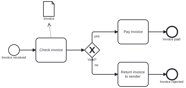
Diagram source
<?xml version="1.0" encoding="UTF-8"?><definitions xmlns="http://www.omg.org/spec/BPMN/20100524/MODEL" xmlns:bpmndi="http://www.omg.org/spec/BPMN/20100524/DI" xmlns:dc="http://www.omg.org/spec/DD/20100524/DC" xmlns:di="http://www.omg.org/spec/DD/20100524/DI" targetNamespace="http://example.com/lifecycle"> <process id="p1" isExecutable="false"> <startEvent id="s1" name="Invoice received"> <outgoing>f1</outgoing> </startEvent> <task id="t1" name="Check invoice"> <incoming>f1</incoming> <outgoing>f2</outgoing> <dataOutputAssociation id="doa1"> <targetRef>d1</targetRef> </dataOutputAssociation> </task> <exclusiveGateway id="g1" name="Valid?"> <incoming>f2</incoming> <outgoing>f3</outgoing> <outgoing>f4</outgoing> </exclusiveGateway> <task id="t2" name="Pay invoice"> <incoming>f3</incoming> <outgoing>f5</outgoing> </task> <task id="t3" name="Return invoice to sender"> <incoming>f4</incoming> <outgoing>f6</outgoing> </task> <endEvent id="e1" name="Invoice paid"> <incoming>f5</incoming> </endEvent> <endEvent id="e2" name="Invoice rejected"> <incoming>f6</incoming> </endEvent> <dataObjectReference id="d1" name="Invoice" dataObjectRef="do1"> <dataState id="ds1" name="checked" /> </dataObjectReference> <dataObject id="do1" /> <sequenceFlow id="f1" sourceRef="s1" targetRef="t1" /> <sequenceFlow id="f2" sourceRef="t1" targetRef="g1" /> <sequenceFlow id="f3" name="yes" sourceRef="g1" targetRef="t2" /> <sequenceFlow id="f4" name="no" sourceRef="g1" targetRef="t3" /> <sequenceFlow id="f5" sourceRef="t2" targetRef="e1" /> <sequenceFlow id="f6" sourceRef="t3" targetRef="e2" /> </process> <bpmndi:BPMNDiagram id="BPMNDiagram_1"> <bpmndi:BPMNPlane id="BPMNPlane_1" bpmnElement="p1"> <bpmndi:BPMNShape id="s1_di" bpmnElement="s1"> <dc:Bounds x="150" y="182" width="36" height="36" /> </bpmndi:BPMNShape> <bpmndi:BPMNShape id="t1_di" bpmnElement="t1"> <dc:Bounds x="240" y="160" width="100" height="80" /> </bpmndi:BPMNShape> <bpmndi:BPMNShape id="g1_di" bpmnElement="g1" isMarkerVisible="true"> <dc:Bounds x="400" y="175" width="50" height="50" /> </bpmndi:BPMNShape> <bpmndi:BPMNShape id="t2_di" bpmnElement="t2"> <dc:Bounds x="510" y="100" width="100" height="80" /> </bpmndi:BPMNShape> <bpmndi:BPMNShape id="t3_di" bpmnElement="t3"> <dc:Bounds x="510" y="240" width="100" height="80" /> </bpmndi:BPMNShape> <bpmndi:BPMNShape id="e1_di" bpmnElement="e1"> <dc:Bounds x="670" y="122" width="36" height="36" /> </bpmndi:BPMNShape> <bpmndi:BPMNShape id="e2_di" bpmnElement="e2"> <dc:Bounds x="670" y="262" width="36" height="36" /> </bpmndi:BPMNShape> <bpmndi:BPMNShape id="d1_di" bpmnElement="d1"> <dc:Bounds x="265" y="40" width="36" height="50" /> </bpmndi:BPMNShape> <bpmndi:BPMNEdge id="f1_di" bpmnElement="f1"> <di:waypoint x="186" y="200" /> <di:waypoint x="240" y="200" /> </bpmndi:BPMNEdge> <bpmndi:BPMNEdge id="f2_di" bpmnElement="f2"> <di:waypoint x="340" y="200" /> <di:waypoint x="400" y="200" /> </bpmndi:BPMNEdge> <bpmndi:BPMNEdge id="f3_di" bpmnElement="f3"> <di:waypoint x="425" y="175" /> <di:waypoint x="425" y="140" /> <di:waypoint x="510" y="140" /> </bpmndi:BPMNEdge> <bpmndi:BPMNEdge id="f4_di" bpmnElement="f4"> <di:waypoint x="425" y="225" /> <di:waypoint x="425" y="280" /> <di:waypoint x="510" y="280" /> </bpmndi:BPMNEdge> <bpmndi:BPMNEdge id="f5_di" bpmnElement="f5"> <di:waypoint x="610" y="140" /> <di:waypoint x="670" y="140" /> </bpmndi:BPMNEdge> <bpmndi:BPMNEdge id="f6_di" bpmnElement="f6"> <di:waypoint x="610" y="280" /> <di:waypoint x="670" y="280" /> </bpmndi:BPMNEdge> <bpmndi:BPMNEdge id="doa1_di" bpmnElement="doa1"> <di:waypoint x="290" y="160" /> <di:waypoint x="283" y="112" /> </bpmndi:BPMNEdge> </bpmndi:BPMNPlane> </bpmndi:BPMNDiagram></definitions>Checks
Section titled “Checks”- Important business objects have their lifecycle drawn as a state machine diagram or statechart.
- Constraints on how processes may change each business object are stated.
- Process events are described as business-relevant states of information objects.
- Where many object instances interact in parallel, the model goes beyond a single activity flow.
Related
Section titled “Related”- State Machine Diagram
- State and Event
- Entity Life Cycle
- Process Notations Comparison (EPC, BPMN, UML Activity Diagram)
- BPMN Data Element
- BPMN Event
- Process Model Complexity
- ARIS Process Views
Sources
Section titled “Sources”- [1408.5094] Verifiable UML Artifact-Centric Business Process Models — ar5iv.labs.arxiv.org, accessed 2026-11-09
- [1303.2554] Artifact Lifecycle Discovery — ar5iv.labs.arxiv.org, accessed 2026-11-09
- Event | ARIS BPM Community — ariscommunity.com, accessed 2026-11-09