Process Analysis and Modeling
Explanation
Section titled “Explanation”A process model describes how work flows through an organization: who takes part, what happens in which order, and what happens when something goes wrong.
Notations. Several notations exist for drawing such models. Two appear here.
- BPMN (Business Process Model and Notation) 2.0 is an industry standard for process modeling and execution. Its notation looks like a flowchart and does not depend on any particular implementation environment. See the article BPMN 2.0 Notation.
- EPC (event-driven process chain) is an ordered graph of events and functions. It is also a notation for business process modeling. See Process Notations Comparison (EPC, BPMN, UML Activity Diagram).
Who uses the models. BPMN is aimed at the people who design, manage, and realize business processes. Its specification asks for enough precision that diagrams can be translated into software process components. That bridges business design and implementation.
One model, two uses. A BPMN process is an XML document that also has a visual form. So the same model can serve as documentation and as an executable artifact.
Actors and responsibilities. BPMN shows participants with pools and lanes. These exist only at the top-level process or collaboration level. They cannot appear inside a subprocess. See BPMN Swimlane (Pool and Lane).
Failure paths. A model should cover more than the smooth case. In BPMN, an event can interrupt a subprocess, whichever step inside it is active. This is how exception paths are modeled.
Example
Section titled “Example”A company models how it handles a customer order. The top-level process has two lanes: sales and warehouse. A “pack and ship” subprocess sits in the warehouse lane. A “customer cancels” event is attached to that subprocess. If the event fires, the subprocess stops, whichever step is running, and the process follows the cancellation path. Business staff read the diagram. The same model can also be handed to a system to run.
Trade-offs
Section titled “Trade-offs”Lanes work only at the top level. Responsibilities inside a subprocess therefore need another way to show them. A model precise enough to execute also takes more care to build than a rough sketch.
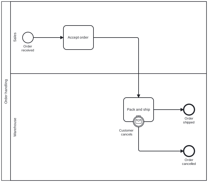
Diagram source
<?xml version="1.0" encoding="UTF-8"?><bpmn:definitions xmlns:bpmn="http://www.omg.org/spec/BPMN/20100524/MODEL" xmlns:bpmndi="http://www.omg.org/spec/BPMN/20100524/DI" xmlns:dc="http://www.omg.org/spec/DD/20100524/DC" xmlns:di="http://www.omg.org/spec/DD/20100524/DI" id="d" targetNamespace="http://example.org"> <bpmn:collaboration id="c"> <bpmn:participant id="p" name="Order handling" processRef="proc" /> </bpmn:collaboration> <bpmn:process id="proc" isExecutable="false"> <bpmn:laneSet id="ls"> <bpmn:lane id="l1" name="Sales"> <bpmn:flowNodeRef>start</bpmn:flowNodeRef> <bpmn:flowNodeRef>accept</bpmn:flowNodeRef> </bpmn:lane> <bpmn:lane id="l2" name="Warehouse"> <bpmn:flowNodeRef>ship</bpmn:flowNodeRef> <bpmn:flowNodeRef>cancel</bpmn:flowNodeRef> <bpmn:flowNodeRef>endOk</bpmn:flowNodeRef> <bpmn:flowNodeRef>endCancel</bpmn:flowNodeRef> </bpmn:lane> </bpmn:laneSet> <bpmn:startEvent id="start" name="Order received"> <bpmn:outgoing>f1</bpmn:outgoing> </bpmn:startEvent> <bpmn:task id="accept" name="Accept order"> <bpmn:incoming>f1</bpmn:incoming> <bpmn:outgoing>f2</bpmn:outgoing> </bpmn:task> <bpmn:subProcess id="ship" name="Pack and ship"> <bpmn:incoming>f2</bpmn:incoming> <bpmn:outgoing>f3</bpmn:outgoing> </bpmn:subProcess> <bpmn:boundaryEvent id="cancel" name="Customer cancels" attachedToRef="ship"> <bpmn:outgoing>f4</bpmn:outgoing> <bpmn:messageEventDefinition /> </bpmn:boundaryEvent> <bpmn:endEvent id="endOk" name="Order shipped"> <bpmn:incoming>f3</bpmn:incoming> </bpmn:endEvent> <bpmn:endEvent id="endCancel" name="Order cancelled"> <bpmn:incoming>f4</bpmn:incoming> </bpmn:endEvent> <bpmn:sequenceFlow id="f1" sourceRef="start" targetRef="accept" /> <bpmn:sequenceFlow id="f2" sourceRef="accept" targetRef="ship" /> <bpmn:sequenceFlow id="f3" sourceRef="ship" targetRef="endOk" /> <bpmn:sequenceFlow id="f4" sourceRef="cancel" targetRef="endCancel" /> </bpmn:process> <bpmndi:BPMNDiagram id="BPMNDiagram_c"> <bpmndi:BPMNPlane id="BPMNPlane_c" bpmnElement="c"> <bpmndi:BPMNShape id="BPMNShape_p" bpmnElement="p" isHorizontal="true"> <dc:Bounds x="80" y="80" width="682" height="596" /> </bpmndi:BPMNShape> <bpmndi:BPMNShape id="BPMNShape_l1" bpmnElement="l1" isHorizontal="true"> <dc:Bounds x="110" y="80" width="652" height="240" /> </bpmndi:BPMNShape> <bpmndi:BPMNShape id="BPMNShape_l2" bpmnElement="l2" isHorizontal="true"> <dc:Bounds x="110" y="320" width="652" height="356" /> </bpmndi:BPMNShape> <bpmndi:BPMNShape id="BPMNShape_start" bpmnElement="start"> <dc:Bounds x="150" y="182" width="36" height="36" /> <bpmndi:BPMNLabel> <dc:Bounds x="138" y="223" width="60" height="28" /> </bpmndi:BPMNLabel> </bpmndi:BPMNShape> <bpmndi:BPMNShape id="BPMNShape_accept" bpmnElement="accept"> <dc:Bounds x="286" y="160" width="100" height="80" /> </bpmndi:BPMNShape> <bpmndi:BPMNShape id="BPMNShape_ship" bpmnElement="ship"> <dc:Bounds x="486" y="400" width="100" height="80" /> </bpmndi:BPMNShape> <bpmndi:BPMNShape id="BPMNShape_endOk" bpmnElement="endOk"> <dc:Bounds x="686" y="422" width="36" height="36" /> <bpmndi:BPMNLabel> <dc:Bounds x="678" y="463" width="53" height="28" /> </bpmndi:BPMNLabel> </bpmndi:BPMNShape> <bpmndi:BPMNShape id="BPMNShape_endCancel" bpmnElement="endCancel"> <dc:Bounds x="686" y="560" width="36" height="36" /> <bpmndi:BPMNLabel> <dc:Bounds x="671" y="601" width="67" height="28" /> </bpmndi:BPMNLabel> </bpmndi:BPMNShape> <bpmndi:BPMNShape id="BPMNShape_cancel" bpmnElement="cancel"> <dc:Bounds x="518" y="462" width="36" height="36" /> <bpmndi:BPMNLabel> <dc:Bounds x="464" y="503" width="65" height="28" /> </bpmndi:BPMNLabel> </bpmndi:BPMNShape> <bpmndi:BPMNEdge id="BPMNEdge_f1" bpmnElement="f1"> <di:waypoint x="186" y="200" /> <di:waypoint x="286" y="200" /> </bpmndi:BPMNEdge> <bpmndi:BPMNEdge id="BPMNEdge_f2" bpmnElement="f2"> <di:waypoint x="386" y="200" /> <di:waypoint x="536" y="200" /> <di:waypoint x="536" y="400" /> </bpmndi:BPMNEdge> <bpmndi:BPMNEdge id="BPMNEdge_f3" bpmnElement="f3"> <di:waypoint x="586" y="440" /> <di:waypoint x="686" y="440" /> </bpmndi:BPMNEdge> <bpmndi:BPMNEdge id="BPMNEdge_f4" bpmnElement="f4"> <di:waypoint x="536" y="498" /> <di:waypoint x="536" y="578" /> <di:waypoint x="686" y="578" /> </bpmndi:BPMNEdge> </bpmndi:BPMNPlane> </bpmndi:BPMNDiagram> <bpmndi:BPMNDiagram id="BPMNDiagram_ship"> <bpmndi:BPMNPlane id="BPMNPlane_ship" bpmnElement="ship" /> </bpmndi:BPMNDiagram></bpmn:definitions>Checks
Section titled “Checks”- Process models use a named, standard notation such as BPMN 2.0 or EPC.
- Actors are shown as pools and lanes at the top-level process or collaboration, not inside subprocesses.
- Exception paths are modeled, for example with events that interrupt a subprocess.
- Where a BPMN model is meant for execution, the same model serves as documentation and as the executable artifact.
Related
Section titled “Related”- BPMN 2.0 Notation
- Process Notations Comparison (EPC, BPMN, UML Activity Diagram)
- BPMN Swimlane (Pool and Lane)
- Levels of Process Modeling
- AS-IS and TO-BE View
- Process Analysis
- Capturing Business Behavior via Process Modeling
- Business Capability
Sources
Section titled “Sources”- BPMN primer | Camunda 8 Docs — docs.camunda.io, accessed 2026-11-08
- About the Business Process Model And Notation Specification Version 2.0 — omg.org, accessed 2026-11-08
- About the Business Process Model and Notation Specification Version 2.0.2 — omg.org, accessed 2026-11-09
- Event-driven process chain - Wikipedia — en.wikipedia.org, accessed 2026-11-09